SensorNet Architectures for Indoor Location DetectionUndergraduate Student: Christopher S. Caplinger Advisors: Ari Trachtenberg, David StarobinskiNeedReliable communication systems are becoming increasingly important for a variety of practical applications. In particular, coordination between equipment and personnel is vital in disaster areas or harsh environments. While well-known tri-lateration techniques, such as GPS, can be effectively utilized in clear, outdoor areas, many real-life environments are unfit for signal propagation (and therefore existing forms of location detection). Therefore, a reliable and robust system of indoor location detection (in harsh environments) is important/useful for many practical applications, such as:
Alternative technologiesOutdoorTri-Lateration (GPS):Functionality:
IndoorInfrared (IR) “Active Badge”Functionality:
Ultrasound (US)Functionality:
Radio (RF) "Fingerprinting"Functionality:
ID-CodesIn general, existing location detection systems lack the robustness needed to protect against equipment failure and changing topology. Proximity-based systems are particularly prone to failure in harsh or dynamic environments, due to the fact that generally, if one sensor is removed or destroyed, the entire system will fail.Project Goals and Requirements
System OverviewThe Identifying Codes-based system can be viewed as a particular case of fingerprinting. In this system, the first step is to divide the coverage area into a finite set of regions, with each region being represented by a single point. These points are then named and mapped to nodes in a graph (figure a). When these physical points are able to directly communicate with one another, the nodes are shown to be connected by lines drawn on the graph (figure b).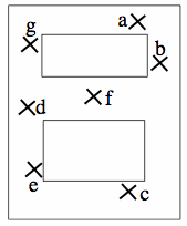 figure a
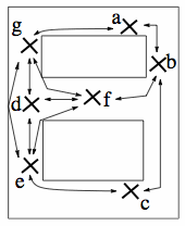 figure b
The problem is then to determine the nodes on which to place and activate the sensors, such that each node is within the communication range of a different set of sensors. For this problem, a greedy algorithm, titled ID-CODE, is utilized. This algorithm produces irreducible ID codes from which no codeword can be removed without violating the unique identification of a position. This algorithm will be further analyzed in the 'ID-CODE Algorithm' section of this page.
figure c shows the sensor placement in the physical coverage area, determined by ID-CODE. Black dots show sensor locations, while X's nodes without sensors.
figure d shows the sensor placement in graphical form, with connections shown as lines between nodes.
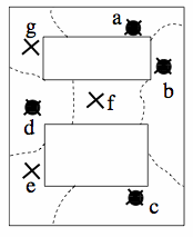 figure c
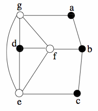 figure d
As can be seen in figures c and d, only a small subset of sensors are activated as beacons. The subset is chosen so that its sensors have an identification property, meaning that a unique (or identifying) collection of these beacons can be detected at any location of interest, with specific regard to physical proximity. In this way, a user can identify its location by simply tallying which beacons it can detect.
As can be seen, significantly fewer sensors are required to cover a localization area. Therefore, redundant sensors can be added to the system to counteract spurious connections or sensor failures, thus increasing the overall robustness of the system.
ID-CODE AlgorithmThe main challenge in designing ID-CODE-based system is to position sensors so that every resolvable location can be identified unambiguously. must find optimal ID code to guarantee that each point selected in a given area is covered by a unique set of transmitters.Testing and ResultsIn order to verify the effectiveness of the ID-Code-based location detection scheme, an experimental testbed was developed. The testbed (located on the 4th floor of the Boston University Photonics Building) utilizes five laptop computers (four as transmitters, one as a receiver) equipped with IEEE 802.11 transceivers. Each transmitter sends 40 packets per second at a rate of 5.5 Mb/s and a transmission power of 100 mW. Shown in figure e, this experimental testbed features ten distinct nodes (identified by white circles) and four transmitters (identified by white circles with X's) with specific locations determined by the ID-CODE algorithm. This contour map also shows the resolution achieved by the location detection system. The map shows resolutions varying from 0 to 70 feet, with darker shades corresponding to a higher resolutions. Although the system consists of only four transmitters, it achieves a reasonable resolution, usually within 50 feet of the correct area. figure f compares the results of the ID-Code-based system with a simple proximity-based location detection scheme. In this scheme, the user's location is defined by the transmitter from which it correctly receives the largest number of packets. figure f shows the CDF of the system resolution for both location detection schemes. As can be seen, a larger number of positions are within the given error distance for the ID-Code-based system. This resolution gain is a direct result of the use of identifying code techniques.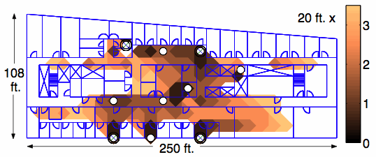 figure e
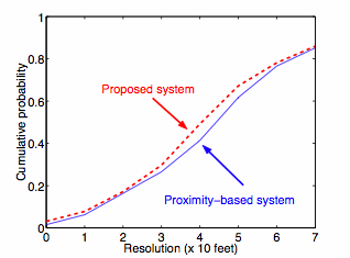 figure f
-- ChrisCaplinger - 25 Nov 2008
|
|
Photonics Building, Room 413
8 St Mary's Street,
Boston MA 02215
Initial web site created by Sachin Agarwal (ska@alum.bu.edu), Modified by Weiyao Xiao (weiyao@alum.bu.edu), Moved to TWiki backend by Ari Trachtenberg (trachten@bu.edu). Managed by Jiaxi Jin (jin@bu.edu).
